
Nozzle design, water pressure, and lead angle are critical for efficient descaling. In the industry, scale removal through water jet descaling using a nozzle lead angle of 15° is considered as optimal.
Download the PDF
T.P. Ojiako1*, V. A. Athavale1, R. Osei2, Taha Tayebali3, Oldair Sasso3, M.F. Buchely1, L. N Bartlett1, S. Lekakh1, R.J. O’Malley1
1Peaslee Steel Manufacturing Research Center, Department of Materials Science and Engineering
Missouri University of Science and Technology, Rolla, MO 65409
2Steel Dynamics Flat Roll Group, Columbus Division
Columbus, MS, USA, 39701
3Spraying Systems Co.
Glendale Heights, IL 60139
*Corresponding author: Tochukwu Princewill Ojiako
Corresponding author email: [email protected]
Phone: (573) 466 2301
Abstract
Nozzle design, water pressure, and lead angle are critical for efficient descaling. In the industry, scale removal through water jet descaling using a nozzle lead angle of 15° is considered as optimal. However, variations in scale removal efficiency were not quantified. Experiments were performed using a laboratory CNC-controlled descaling system. Low- alloy steel plates were reheated at 1065°C in an atmosphere-controlled induction furnace and then descaled using two nozzle types and three attack angles in all cases. Statistical characterization of residual oxide coverage was performed using SEM analysis in a crosssection of the plate. Recommendations to increase descaling efficiency are presented.
Keywords: Descaling, Oxides, Nozzles, Attack-angle, SEM
Introduction
Oxide scale growth due to high-temperature oxidation during steel making process is an unavoidable challenge in the industry. This phenomenon presents limitations for final finishing processes. Studies have shown that over 5 pct. of hot rolled metal (plates/sheets) are internally recycled due to residual oxide scale and this disrupts other downstream manufacturing processes [2]– [8]. Scale removal is a necessary part of the steel-making process. The surface quality of the reheated billets depends on the efficiency of the descaling process, especially in continuous casting (CC) where hot rolled sheets and plates with as-cast surfaces are subjected to a reheating process.
The special nozzles incorporated into a high-pressure water system are used for in-line descaling. A high-pressure descaling involves a powerful pump that intensifies the pressure of the water, which is propelled through a nozzle at high velocity. The high-pressure water stream is directed at the surface to be cleaned, and the force of the water is strong enough to blast away oxide scale and dirt. Practical observations of the high-pressure hydraulic descaling process indicated that impact pressure, water consumption, and lead angle are the most important factors affecting descaling efficiency. Given the multilayer structure of a typical scale structure with randomly oriented defects (porosity and cracks) the mechanism of descaling process is very complicated [2], [8]– [14]. Three major descaling mechanisms are considered: (i) mechanical hammering by water droplets, (ii) shear forces, and (iii) localized in defect exploded high- pressure water vapor. The first two mechanisms are considered to be major, depending on water jet surface interaction, and could be controlled by the descaling system design.
The motivation for this work is to establish the influence of nozzle design and lead angle on the efficiency of oxide scale removal in the steel-making process.
Experimental Procedure
To simulate a complete industrial process, a set of experimental procedures was used and included (Figure 1). The study of the effect of nozzle type and lead angle involves 3 distinct processes with microstructural analysis:
- Collecting industrial continually cast slab with an original as-cast surface
- Reheating in control atmosphere to mimic the industrial reheating process
- Laboratory descaling of hot reheated slab with a CNC-controlled high-pressure water jet setup
- SEM measurement of residual scale

Figure 1. Illustration of the experimental setup
For this study, low alloy steel with the composition shown in Table 1. Section of a continuously cast slab with one (top) original as-cast surface was cut into 164mm * 84mm * 20mm specimens.
| Table 1. The Composition of the Slab (wt. %) |
|||||
| C | Mn |
Si | Cu | Ni | Cr |
| 0.068 | .037 |
0.025 | 0.10 | 0.038 | 0.062 |
The industrial reheating condition was simulated using a 35(kW) lab-scale induction melting furnace (Model LSZ-35) with a 229mm * 104mm * 45mm enclosed heating chamber to achieve a controlled atmosphere for the reheating process. The reheating atmosphere of industrial furnace gas was reproduced in the lab condition, using a mass flow meter- controlled gas mixture. To avoid gas starvation and boundary-controlled reaction step a high 6000ml/min gas flow rate which provided ~2cm/sec gas flow velocity was used. Several gas inlets were placed in the reheating chamber to evenly distribute the gas stream. A Land Lamcom III portable multi-gas analyzer was used to quantify the oxygen supplied within the chamber and adjust it to the desired concentration. Hot water double bubbler was used to saturate water vapor in gas steam. The temperature, time, and atmospheric conditions are presented in Table 2.
| Table 2. The Simulated Industrial Reheating Conditions | ||
| Equilibrating temperature, °C |
Atmospheric condition, vol. % |
Hold time at reheating temperature, min |
| 1065 | 2O₂+ 8.6 CO₂ + 72.2 N₂ + 17.2 H₂O; |
20 |
Figure 2 shows an example of a reheating curve temperature that was obtained during one of the trials. This figure also shows the initial slab before reheating, and during reheating inside the induction furnace chamber. The side hole in the slab is the place where the thermocouple was inserted to track the temperature.
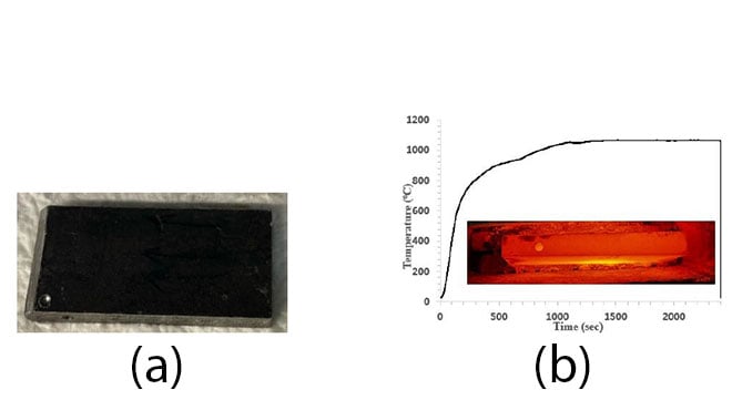
Figure 2. (a) Initial as-cast condition of the thin slab, and (b) Thermal profile for the reheating test and reheated thin slab in an induction heater chamber.
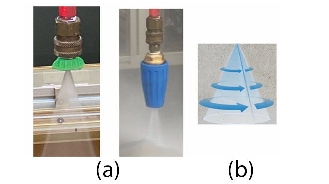
Two different nozzle types were incorporated into the existing CNC-controlled descaling chamber separately (Figure 3). The first one (Figure 3a) was a common flat nozzle with a 25° spray angle that creates a narrow rectangular jet footprint and was rated 4 gpm flow rate at a maximum of 4500psi pressure. The second nozzle was a turbo rotary nozzle (Figure 3b) with a rated 2.5 gpm flow rate at 4500 psi pressure. This nozzle creates a hollow circular jet footprint. The nozzles were installed in three different lead angles: 0°, 15°, and 25°, inclined to the vertical axis. This was done to study the effect of the nozzle lead angle on the scale removal efficiency.
After reheating, the hot slab was transferred to the descaling chamber where the as-cast surface was exposed to hydraulic descaling. CNC provided desired one-pass profile with a velocity of 2 m/min. The slab was immediately quenched after the descaling pass.
The width of the descaled pass was measured from the top view and Mahr federal portable perthometer (M1) was used to measure average Ra roughness at the middle of the pass. After that, the descaling footprint was coated with epoxy resin and a water jet cut was used to extract 15mm × 20 mm specimens at the middle of the descaled footprint. The micro-structural imaging and EDX analysis were performed using SEM ASCAT and TESCAN.
Results and Discussion
Structure of As-Cast Surface
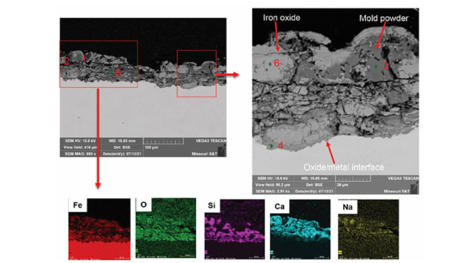
Analysis of the as-cast surface structure of the steel used in this study is shown in Figure 4. Examined in cross-section the as-cast scale structure before reheating consisted of two well-defined scale layers, external and internal [8]. The external scale layer (outer) had micro and macro cracks in the transverse and lateral directions. The external layer also had voids and porosities close to the outer surface. The internal scale layer included also mixed oxide/metal subsurface located at the scale/matrix interface. This layer appeared to be strongly adherent to the metal substrate. The overall thickness of the as-cast surface scale layer measured between 40 – 75 μm. Point EDX chemistry analysis of the as-cast surface structure revealed the presence of Ca-based oxide, a typical indication of mold powder residue (points #1, #3, and #5). The presence of this complex Ca-based oxide chemistry has been reported to modify oxide scale chemistry and its removal ability [8]. The mold powder residue (oxide jacket) on the as-cast slab surface was intertwined with iron oxide formation as observed in the structural differences with lower levels of Ca (points #2 and #6). The presence of the complex mixture of mold powder residual and iron oxide on the as-cast slab surface was seen in the external scale layer through to the subsurface scale layer. In the subsurface scale layer, the oxide structure was smooth with fine grains, having strong adhesion to the oxide/metal interface. EDX mapping revealed the distribution of elements in the as-cast surface scale structure.
| Table 3. Oxide Scale Composition of As-Cast Surface (wt.) in Points From Figure 4 |
|||||||||
| Point | Fe |
O | Si | Mn | Mg | F | Na | Al | Ca |
| 1 | 11.0 |
28.0 | 20.0 | 1.0 | 3.0 | - | 2.0 | 3.0 | 32.0 |
| 2 | 76.0 | 22.0 | - | 1.0 | - | - | - | - | 1.0 |
| 3 | 11 | 25.0 | 18.0 | - | - | - | 2.0 | 2.0 | 42.0 |
| 4 | 58.0 | 26.0 | 8.0 | 1.0 | - | - | - | 1.0 | 6.0 |
| 5 | 4.0 | 20.0 | 16.0 | - | - | 4.0 | - | - | 56.0 |
| 6 | 74.0 | 21.0 | - | 1.0 | - | - | - | - | 4.0 |
Scale Structure of the Reheated As-Cast Surface
Reheating the steel sample with an as-cast surface promoted scale modification and defect formation between the external scale layer and the internal subsurface scale layer, as shown in the cross-sectional microstructure (Figure 5). The external scale layer was saturated by voids forming in the inner section of the external scale layer. The internal/subsurface scale layer consists of a mixture of iron oxide and silicon-based oxide with a trace presence of Ca in the scale chemistry (point #2 in Figure 5). This complex formation in the subsurface had an iron oxide layer superimposed on a silicon-base oxide layer. The silicon-based oxide penetrated the metal substrate. The presence of Si-based oxide in the subsurface scale chemistry was unexpected since the steel contained no significant amount of Si (0.01 wt.%) to promote its formation. However, the presence of Si-based oxide in the subsurface suggests that the complexity of the subsurface layer formation was promoted by mold powder residue which contains high levels of silica in its chemistry as reported in Figure 5 EDX point #3 on the as-cast surface scale analysis. This analysis indicated that reheated as-cast surface consisted of a mixture of complicated oxides with different defects and adhesion ability to steel surface. The distribution of subscale thickness after reheating is shown in
Figure 6. It can be seen that the distribution of the scale is given by two main peaks: one around 10 μm and other around 50 μm.
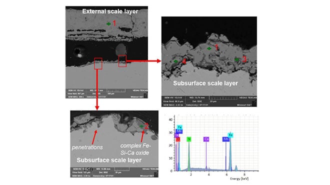
Figure 5. SEM analysis of cross-section of scale structure formed on as-cast surface after reheating: top-left (scale structure after reheating, low magnification), top-right & bottom left (scale structure after reheating, high magnification) bottom-right (EDX spectrum from point 2).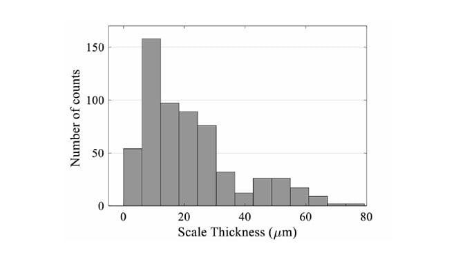
Descaling Tests
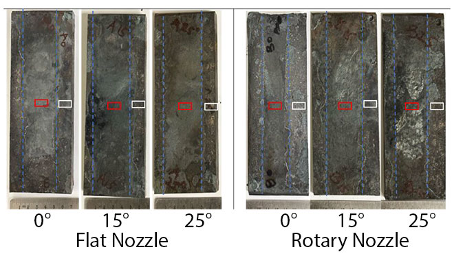
Figure 7 illustrates a top view of descaled plates and Table 4 presents the numerical data obtained from descaled slabs before sectioning for SEM analysis. The segmented lines represent the visually estimated width of descaling passes, while an average thickness and standard deviation were determined from the measured seven measurements. It was found that the flat nozzle produced slightly wider passes compared to the rotary nozzle and increasing the lead angle increased the descaling pass width for both nozzles. In addition, weight loss after descaling was measured for a general estimation of the descaling process. Increasing lead angle increased weight loss due to the descaling mechanism for two nozzles which recorded better scale removal especially 15° lead angle. Roughness (Ra) values seem to be less at 15° lead angle for two nozzles. These results indicated a positive effect of using a lead angle compared to a straight water jet attack.
| Table 4. Summary of Measurements After Descaling Pass for Each Study Condition |
||||||
| Nozzle | Flat | Rotary |
||||
| Lead angle (°) | 0 |
15 | 25 | 0 | 15 | 25 |
| Pass width (mm) | 40±5 | 49±3 | 44±5 |
30±3 | 49±5 | 40±4 |
| Roughness (Ra) | 7±1 | 5±1.5 | 9±3.6 | 8±2 | 5±0.5 | 11±2 |
| Weight loss (g) | 30 | 34 | 32 | 25 | 33 | 32 |
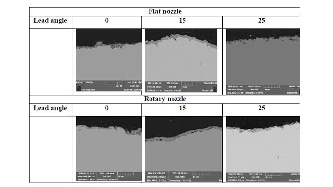
Detailed evaluation of descaling efficiency was performed by SEM measured of residual scale in cross sections and statistical analysis of probability distribution of scale thickness within the descaling footprint. An overview of the residual scale after descaling with different lead angles and nozzle design is shown in (Figure 8).
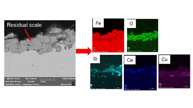
A typical region with mildly oxidized surfaces is shown in (Figure 8) at large magnification. Most residual scale thickness ranges from 2-10 μm while in some places the oxide scale with deep penetration measured up to 20 μm. The residual scale had the presence of mixed oxides. Chemistry analysis revealed the possible presence of Fe-Si-Ca-based oxides. A higher magnification of this scale layer coupled with elemental mapping showed the distribution of Fe-Si-Ca elements in the oxide scale.
Many representative images were taken from each condition; thus, the residual scale was measured from all the taken images. Figure 10 showed averaged results using a box diagram. It could be seen that the thickness of the residual scale has a wide distribution and averaging statistical analysis did not provide visible evidence to conclude the effect of studied parameters on descaling efficiency.
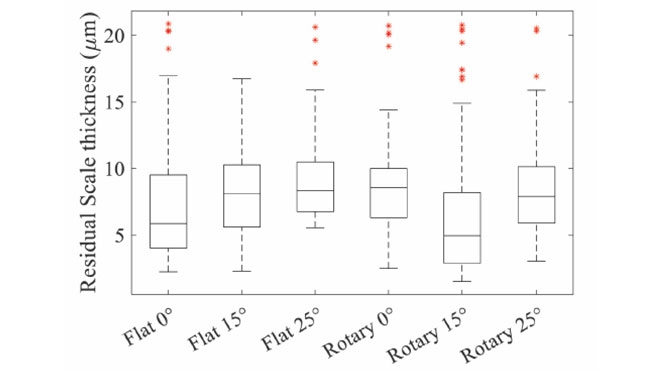
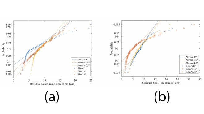
From a descaled surface quality point of view, the most important quality parameter is related to the existence of unremoved spots with large thickness of the scale. A critical scale thickness could be between 10 and 15 microns. Therefore, a detailed statistical analysis of nozzle efficiency and the effect of lead angle was done by plotting the probability curves to determine the amount of residual scale above a critical limit (Figure 11). In general, it can be noticed that all distributions had a deviation from normal (segmented straight lines) at high thickness. For a flat nozzle, a larger negative deviation above 15 microns was observed for straight to surface lead angle. The best distribution was observed for 15⁰. Such lead angle efficiently removed scale for all spectrums of thicknesses and residual thickness had near normal distribution. Increasing the lead angle to 25 ⁰ was less efficient for small and large residual scale thicknesses. Rotary nozzle descaling efficiency was slightly better at zero lead angle and increasing lead angle left more spots with thickness above critical values determined in this article. For rotary nozzles normal to surface distribution had positive statistical effect.
From the results obtained, flat and rotary spray nozzles exhibited different descaling results possibly due to the mechanism of water jet interaction with scale, which also depended on the lead angle. Nozzle design and attack angle have a direct effect on the descaling performance because of the mechanisms associated with the orientation of vector force acting on the point of impact [1,9].
Conclusions
- Nozzle design and lead angle play a vital role in effective oxide scale removal because initiated different mechanisms of scale failure and detachment from the steel surface
- Regular flat jet nozzle provided the best descaling efficiency at the 15° lead angle because initiated shear mechanism in addition to droplet hammering as reported by [9].
- The rotary nozzle showed the capability to high descaling because of fluctuation of droplet attack angle in addition to lead incline which activated crack propagation of randomly oriented cracks in scale. Also, the descaling efficiency of the rotary nozzle is less dependent on the nozzle lead angle.
- Future studies will be performed using additional special methods, such as force measurement, surface erosion, and cold vs hot descaling to look at in-depth steel descaling mechanics.
Acknowledgment
This study is supported by Peaslee Steel Manufacturing Research Center (PSMRC), and the authors wish to acknowledge the support, guidance, and contributions of the industrial board members especially Spraying Systems Co. and Steel Dynamics Inc.
References
- L. Robb, “Experts in Spray Technology Spray Nozzles Spray Control Spray Analysis Spray Fabrication Effect of Spray Height, Lead Angle and Offset Angle on Impact Effect of Spray Height, Lead Angle and Offset Angle on Impact,” 2005. [Online]. Available: www.sprayconsultants.com
- M. Schütze, W. Melfo, and E. Barabino, “Oxi 2018 European Oxide Scale Conference Experimental determination of the critical strain of fracture of oxide scale in hot finishing mill conditions using the sigma test.”
- R. M. P. Huitron, P. E. R. López, E. Vuorinen, P. N. Jalali, L. Pelcastre, and M. Kärkkäinen, “Scale formation on HSLA steel during continuous casting part I: The effect of temperature–time on oxidation kinetics,” Metals (Basel), vol. 10, no. 9, pp. 1–22, Sep. 2020, doi: 10.3390/met10091243.
- R. M. P. Huitron, P. E. R. López, E. Vuorinen, P. N. Jalali, L. Pelcastre, and M. Kärkkäinen, “Scale formation on HSLA steel during continuous casting part ii: The effect of surface conditions,” Metals (Basel), vol. 10, no. 9, pp. 1–19, Sep. 2020, doi: 10.3390/met10091245.
- S. A. Arreola-Villa, H. J. Vergara-Hernández, G. Solorio-Diáz, A. Pérez-Alvarado, O. Vázquez-Gómez, and G. M. Chávez-Campos, “Kinetic Study of Oxide Growth at High Temperature in Low Carbon Steel,” Metals (Basel), vol. 12, no. 1, Jan. 2022, doi: 10.3390/met12010147.
- X. Yu, Z. Jiang, J. Zhao, D. Wei, C. Zhou, and Q. Huang, “Effect of a grain-refined microalloyed steel substrate on the formation mechanism of a tight oxide scale,” Corros Sci, vol. 85, pp. 115–125, 2014, doi: 10.1016/j.corsci.2014.04.006.
- R. Y. Chen and W. Y. D. Yuen, “Review of the High-Temperature Oxidation of Iron and Carbon Steels in Air or Oxygen,” 2003.
- R. Osei, “Scholars’ Mine Scholars’ Mine Scale formation, properties and de-scaling in steelmaking Scale formation, properties and de-scaling in steelmaking,” 2022. [Online]. Available: https://scholarsmine.mst.edu/doctoral_dissertations/3157
- M. Raudensky, A. Horak, J. Horsky, M. Pohanka, and P. Kotrbacek, “Amélioration du décalaminage hydraulique, structure du jet et effet «coup de bélier»,” 2007.
- M. Pohanka, P. Kotrbacek, E. Bartuli, and M. Raudensky, “Energy-Efficient Cooling and Hydraulic Descaling Systems,” Metallurgist, vol. 64, no. 7–8, pp. 729–740, Nov. 2020, doi: 10.1007/s11015-020-01050-4.
- L. Bendig, M. Raudenský, and J. Horský, “Descaling with High Pressure Nozzles,” 2001.
- M. Degner, “3rd international conference on hydraulic descaling Rolling technology View project Measuring technique View project,” 2001. [Online]. Available: https://www.researchgate.net/publication/294861874
- J. Wen and C. Chen, “Optimizing the structure of the straight cone nozzle and the parameters of borehole hydraulic mining for Huadian oil shale based on experimental research,” Energies (Basel), vol. 10, no. 12, Dec. 2017, doi: 10.3390/en10122021.
- Horsky, J., Raudensky, M., & Vavrecka, L. (2007). Experimental study of hydraulic descaling. HEFAT 2007.