
Spray dry nozzles represent a notable portion of industrial atomizers and are typically used to generate a dried powder from a liquid or slurry. In this study, nozzles which are used for spray drying in areas such as the dairy, food, pharmaceutical, and chemical industries, are characterized and analyzed over a range of operating conditions.
Download the PDFOn SprayDry® Nozzle Flow Path Effects on Atomization and the Influence of Fluid Viscosity
K. M. Bade*, N. Haroutunian, J. Shen, and R. J. Schick
Spray Analysis and Research Services, Spraying System Co., USA
Spraying System Co., China
*Corresponding author: [email protected]
Abstract
Spray dry nozzles represent a notable portion of industrial atomizers, and are typically used to generate a dried powder from a liquid or slurry. From a spray technology perspective, these nozzles are identified as pressure-swirl nozzles that operate at high pressures in order to generate relatively small droplets with controlled distributions. In this study, nozzles which are used for spray drying in areas such as the dairy, food, pharmaceutical, and chemical industries, are characterized and analyzed over a range of operating conditions. Parameters of interest include nozzle type (Swirlchamber, Whirlchamber, and Slotted Core) and material viscosity, where water-based mixtures with viscosities of 1, 1000, and 5000 cP are investigated. For the experiments, a Phase Doppler Interferometer instrument is used to acquire drop size, velocity, and concentration information, while the modeling effort was conducted using the ANSYS Fluent package. Traditionally difficult measurements due to high spray density, the detailed test results across each spray plume provide insight on the spray characteristics over the range of operating conditions. The detailed computational models of the internal flow paths of each nozzle type reveal upstream velocity characteristics which are responsible for generating the downstream spray characteristics. Greater understanding of the upstream flow characteristics, and downstream spray characteristics, allows for improved nozzle selection and design to achieve targeted performance, atomization, and efficiency.
Introduction
The spray drying process has been employed in industrial applications in the dairy, food, pharmaceutical, and chemical industries for many years. In practice, spray drying involves atomization of a liquid mixture into small droplets that are then ‘dried’ to generate a powder. In order to maximize the efficiency of evaporation of the water portion of the liquid, fine atomization is preferred to create a large surface area to volume ratio of the drying liquid. The Sauter Mean Diameter (SMD or D32), which is representative of the total volume to surface area ratio of the sprayed liquid [1] [2], is commonly used to evaluate the expected drying efficacy because as this ratio decreases (and D32 decreases) the droplets will dry faster. The drying process typically takes place in a chamber where flowing gas is introduced to promote evaporation; heat may also be added to increase the drying efficiency. The end result of the spray dry process is a dried particulate product, made up of the components originally mixed in liquid form. For a comprehensive review of the spray drying process, the reader is encouraged to review the Spray Drying Handbook by K. Masters [3].
Common nozzles used for spray drying are characterized as pressure-swirl atomizers, which use the internal nozzle geometry, along with relatively high liquid pressure (energy), to atomize the fluid into very small droplets in a full or hollow cone spray pattern. Atomization in spray dry processes aims to not only to achieve small droplets, but also to produce narrow-width drop size distributions [3], and to avoid large droplets that may not fully dry within the allotted process domain. Coaxial air-blast atomizers for spray drying applications, specifically pharmaceutical tablet coating processes, have received extensive attention [4] for the atomization of viscous and non-Newtonian materials [5, 6] and do allow effective atomization with narrow drop size distributions. However, pressure-swirl atomizers do not use a secondary fluid to promote liquid breakup, thus providing a simpler solution, and allowing larger material throughput. Stahle et al. [7] investigated spraying of food-industry liquids with both pressure-swirl and twin-fluid nozzles, finding improved atomization efficiency with pressure-swirl nozzles with low viscosity fluid, but requiring twin-fluid nozzles to adequately atomize higher viscosity materials. To better understand the mechanisms leading to breakup, or lack of, in pressure-swirl nozzles, Lee et al. [8] used low viscosity fluid (diesel, kerosene) to examine the internal air-core and related fluid turbulence, and categorized the unstable/stable flow regimes and built upon earlier drop size measurements by Lefebvre and Wang [9]. Furthermore, Dafsari et al. [10] examined the effects of the swirl chamber length on the resulting spray, using water, finding that a shallow length resulted in a hollow cone spray, while a taller swirl chamber length produced a full cone spray due to a shift in the fluid concentration toward the exit orifice centerline rather than the edges. These investigations are instructive, however, they focus on liquids of very low viscosity (≤1 cP), and therefore offer limited use for highly viscous material sprays. Bloore [11] provides an study of the effects of fluid viscosity on pressure-swirl nozzles, where he finds that nozzle geometry can play a significant role in spray formation and the level of effect fluid viscosity has on the nozzles pressure/flow performance as well as the spray characteristics.
| Nozzle (abbr.) |
Part Number | Orifice Diameter | Internal Component | P | Q | |||
| mm | (in.) | bar | (psi) | lph | (gph) | |||
| SV-6 | SVI-106YM+SVS6 | 2.70 | (0.106) | Swirlchamber | 70 | (1000) | 722 | (189) |
| SB-40 | SIBY40+SBBY32-MFP | 2.50 | (0.098) | Slotted-Core | 70 | (1000) | 736 | (193) |
| AA-2 | AA104-1/2-AA-TCX2-8 | 4.00 | (0.156) | Whirlchamber | 70 | (1000) | 744 | (193) |
Table 1: List of nozzles used for testing with abbreviated names, full part numbers, exit orifice diameters, internal geometry type, and rated pressure/flow performance. Note, while the abbreviations used here for each nozzle use a single numeral identifier, each nozzle incorporates 2 parts (the orifice and the insert), which are fully identified in the Part Number column.
Spraying Systems Co. began designing and manufacturing spray dry nozzles at the beginning of the spray dry process adoption, and offers a wide array of SprayDry® nozzle types and capacities to accommodate nearly any application. The drop size distribution produced by each pressure-swirl spray drying nozzle will typically depend on the pressure, capacity, nozzle geometry, and liquid rheology (density, viscosity, and surface tension). For the purposes of this investigation, the results will focus on nozzle geometry and liquid viscosity variations, which expand upon previous investigations by Bade et al. [12],[13]. The results of the present study demonstrate the importance of material viscosity, and Newtonian/non-Newtonian properties, when evaluating the optimal nozzle for a spray dry process.
Experimental Methods
Nozzles
The investigations carried out in this study include pressure-swirl nozzles commonly used in spray drying processes and manufactured by Spraying Systems Co. All nozzles were selected based on similar atomization technologies and targeted to provide similar flow rates at the same operating pressure with water for simple comparison, approximately 725 lph at 70 bar, the details of which are noted in Table 1.
Three types of Spraying Systems Co. SprayDry® nozzles were used, the primary distinction between these nozzles is the internal flow path geometry, defined by using a Swirlchamber, Slotted-Core, or Whirlchamber; identified as the SV, SB, and WhirlJet® (AA) nozzles, respectively. Figures 1-3 show an example of each nozzle body and the associated internal components of each type of nozzle; more information on these nozzles is available in the Spraying Systems Co. SprayDry® nozzle catalog, Bulletin No. 695A [14].
The SV SprayDry nozzle uses a Swirlchamber, creating a flow path that forces the liquid to enter a shallow (axially) chamber which imparts a radial flow velocity in the fluid before exiting through a round orifice. Figure 1 provides an image of the assembled SV nozzle body, Swirlchamber, and exit orifice insert.
The SB SprayDry nozzle uses a Slotted-Core which generates a rotating fluid by forcing the fluid through angled slots around the outer surface of the Slotted-Core, before exiting through a round orifice. Figure 2 provides an image of the assembled SB nozzle body, as well as the Slotted-Core and exit orifice insert.
The WhirlJet SprayDry nozzle directs the liquid through one, or two, off-center entry ports on the Whirlchamber into a tall (axially) chamber which imparts a radial flow velocity in the fluid before exiting through a round orifice. Figure 3 provides an image of the assembled WhirlJet SprayDry nozzle body, as well as the Whirlchamber and exit orifice insert.
Each of the SprayDry nozzle types carries its own benefits and limitations over the rated flow rate range, resulting in differences in spray angle, volume distribution, droplet velocity (residence time), and drop size distribution; which are examined in this investigation. The SV SprayDry nozzle allows the lowest minimum rated flow rate (1-60 lpm at 70 bar), the SB SprayDry nozzle has the smallest low-to-high rated flow rate range (3.5-35 lpm at 70 bar), and the WhirlJet SprayDry nozzle provides the widest rated flow rate range (3.3-85 lpm at 70 bar). The purpose of this investigation is to investigate the details of the spray characteristics with each nozzle style, and to provide an explanation for the benefits, given the relative similarly of each design.
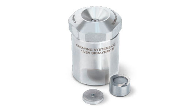
Figure 1: SV SprayDry nozzle body, with a Swirlchamber and orifice insert
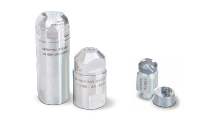
Figure 2: SB SprayDry nozzle bodies (left), with a Slotted-Core and orifice insert (right)
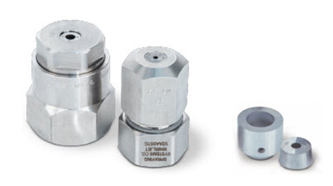
Figure 3: WhirlJet SprayDry nozzle body (left), with a Whirlchamber and orifice (right)
Spray Material
In order to investigate the effects of material viscosity on the resulting spray characteristics using these SprayDry nozzles, three material mixtures were used. The first, standard tap water, was confirmed to have a viscosity of 1.00 cP at a test temperature of 20°C. For the other two material viscosities, a mixture of water and methylcellulose (water+MC) was used to create materials with viscosities of 1000 & 5000 cP. The primary advantage of using dissolved methylcellulose to generate the increased viscosity material is that the resulting material density and surface tension remain essentially the same as pure water, and the three testing materials i) water and ii) water+MC at 1000 cP, and iii) water+MC at 5000 cP can be used to isolate the effects of viscosity differences. Furthermore, methylcellulose is a non-toxic material making it attractive in open-lab testing efforts. For the present work, methylcellulose manufactured by Dow Chemical was used. For a detailed review on the mixing and properties of methylcellulose, the reader is referred to the open-source review article by Nasatto et al. [15].
However, it was found that while the water+MC mixtures behaved in a Newtonian way at the relatively low shear rates of the rotating spindle viscometer, at the much higher shear rates inside the nozzle, the water+MC can behave in a very non-Newtonian manner. These effects are discussed in more detail through this report.
Figure 4 provides the rated performance curve, pressure vs. flow rate, for the three nozzle styles and selected chamber/insert sizes. The curves are provided for water-based performance, and the symbols demonstrate the measured flow rate at 70 bar for each nozzle, and the measured flows agreed very well with the rated flow rates at this pressure.
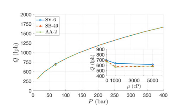
Figure 4: Pressure (P) vs. flow rate (Q) for each nozzle and material. The inset figure shows the flow rate over 3 dynamic viscosities (μ ) and the resulting flow rate when sprayed at 70 bar.
The Figure 4 inset-axis provides the flow rate for each nozzle with material viscosities of 1, 1000, and 5000 cP. It can be seen that all nozzles demonstrate a reduction in flow rate from 1 to 1000 cP when operated at 70 bar (1000 psi). The SV nozzle further decreases in flow rate with 5000 cP material, while the SB and AA nozzles recorded nearly the same flow rate, but actually a 1.6% increase, an effect that will be discussed in the results section.
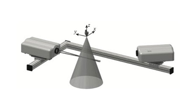
Figure 5: PDI and nozzle setup with coordinate system definition
Phase Doppler Interferometry
Phase Doppler Interferometry (PDI) measurements were acquired, using an Artium Technologies PDI-MD-300 instrument to provide measurements of droplet size, velocity, and local volume flux. Similar acquisition methods were used as those outlined as optimal by Bade and Schick [16], with the transmitter/receiver lens combination of 1000/1000 mm, and the receiver located at a 40° off-axis position, which allowed for a sufficient drop size measurement range and resolution. 5,000-10,000 samples were acquired at each point to provide converged statistical values (±1%). Bade and Schick [16] also provide an extensive investigation of the accuracy of volume flux measurements using the PDI instrument which were found to be accurate to within approximately 2% when proper droplet trajectory considerations are used in the data collection methods. The ability of the PDI instrument to simultaneously measure local drop size, velocity, and flux provides an attractive source of point measurements within a spray plume; and the methods outlined by Bade and Schick [17, 18] allow these point measurements to be used to generate planar spray characteristics for more general comparisons. As a matter of practicality, all PDI measurement points were acquired at a single distance from the nozzle (z=-600 mm), and at constant intervals from the nozzle center point along a single radial path (+x). Figure 5 demonstrates the testing setup for these investigations as well as the coordinate systems with (x,y,z)=(0,0,0) defined at the center of the nozzle exit orifice.
The pointwise PDI data were post-processed into weighted averaged results to arrive at concise and meaningful general planar statistics. The methods used to generate weighted average values which are representative of the planar spray plume characteristics follow typical mathematical processes, and are identified in detail by Bade and Schick [18]. For the purposes of this paper, two weighting parameters are used in the post-processing of the pointwise data and each represents a relevant physical characteristics of the investigated spray plumes: i) the discrete area that each measurement point is expected to represent, and ii) the local volume flux at the location of each measurement. The use of the two parameters together weight the averaged results toward the spray characteristics where the majority of the sprayed volume is present. Common drop size statistics and distribution terminology is used throughout these analyses; the unfamiliar reader is directed to the ubiquitous text by Lefebvre [2].
Computational Methods
For the computational modeling effort, the ANSYS Fluent software package was used to solve the fluid flow field. The solver was pressure-based steady flow with gravitational acceleration enabled and turbulence modeled as realizable k-ε with standard wall function. Boundary conditions were set with an inlet velocity of 0.8475 m/s (equal to 736 lph) for a water flow with viscosities of 1, 1000, and 5000 cP (0.001, 1, and 5 k g/m-s). The computational domain was meshed using ANSYS Meshing, with a mesh element count of approximately 3,375,000. Tetra element type was used, max element size was set as 0.002m, five inflation layers with 1.05 growth rate, and the first layer height equal to 0.02 mm to capture the flow features near the walls. Even fine mesh resolution was used to capture the flow field near the nozzle exit by controlling the local mesh element size to be no larger than 0.12 mm, and max skewness less than 0.93 with minimum orthogonal of more than 0.13.
Results and Discussion
As described in the Introduction, this work began as an experimental effort to determine differences in the spray characteristics and performance of various spray dry nozzles with under a range of material viscosities [12] [13]. The goal of the present effort is to expand upon the experimental results by adding more viscous 5000 cP material to the experimental investigations. Additionally, a parallel effort was conducted using computational modeling methods to better understand and explain the flow inside the nozzle, which leads to the resulting downstream spray characteristics.
PDI testing was conducted for each of the three nozzles, at a single spray distance along a single radial axis; from the center to the edge of the spray. While the pointwise data are instructive, only the weighted average results are presented here for brevity; the PDI testing results are presented in Figures 6 - 7.
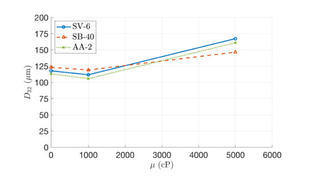
Figure 6: Sauter Mean Diameter (D32) for each nozzle vs material dynamic viscosity (μ).
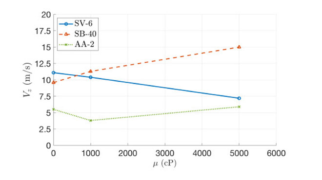
Figure 7: Axial Velocity (Vz) for each nozzle vs material dynamic viscosity (μ).
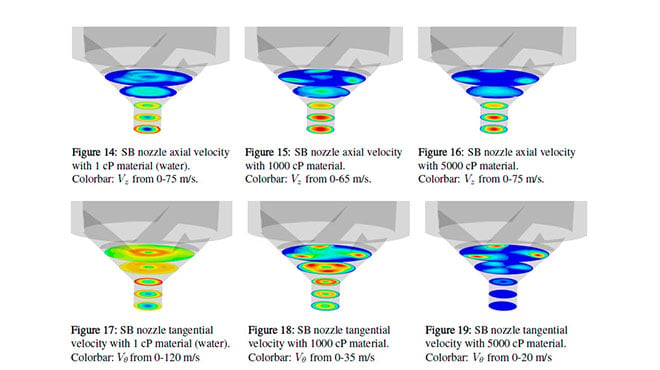
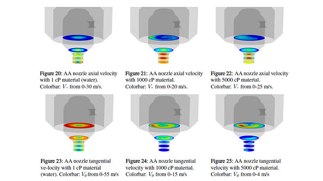
The first-impression result in Figure 6 is the relative similarity of the D32 drop size across all three nozzles at each viscosity, at this particular operating condition with this material. Each nozzle demonstrates a small decrease in drop size from 1 to 1000 cP followed by a large increase from 1000 to 5000 cP; this does not follow the obvious trend of increasing drop size with viscosity. It is known that a water and methylcellulose can exhibit shear-thinning non-Newtonian characteristics at high shear rates, and it is expected that the shear rate inside the nozzle swirl cavities is the cause of this approximately 5% decrease in drop size with 1000 cP material. The 5000 cP material is viscous enough to create a larger drop size of about 30-40% over the 1 cP water. Also, as shown in the modeling results of Figures 8-25, there is a shift in the tangential velocity inside the nozzle where the flow velocity is highest near the wall at 1 cP, but is highest along the nozzle centerline at 1000 and 5000 cP.
The velocity results vs. viscosity, shown in Figure 7, exhibit very different trends for the three nozzles, and do not simply follow the expected trend of decreasing velocity with increasing viscosity. The results of Figure 4 demonstrate that, the flow rate through each nozzle does not simply reduce with increasing viscosity as would be expected with a Newtonian fluid. The SV flow rate does monotonically decrease with viscosity, but the SB and AA flow rates decrease from 1 to 1000 cP, but increase slightly from 1000 to 5000 cP.
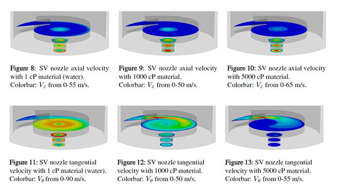
For the SV nozzle, the flow rate and velocity trends of decreasing with increasing viscosity follow with traditional Newtonian fluid flow trends. As can be seen in the modeling results Figures 8-13, the fluid flow enters the Swirlchamber tangentially, swirling and exiting the exit orifice with an edge-concentrated flow for the 1cP case and a center concentrated flow with the high viscosities. Additionally, the concentration of the high velocities in the exit-jet center is higher for the 5000 cP flow, which leads to the conclusion that with the higher viscosities, this Swirlchamber is minimally influential and a converging jet is created. This shift in character of the exiting flow is likely due to the limited space allowed for the shallow Swirlchamber to impart significant tangential velocity into the flow.
The AA nozzle uses a Whirlchamber design, which is similar in concept to the SV Swirlchamber, but the AA allows for a much larger flow to be contained in the Whirlchamber before exiting. The velocity trend for the AA nozzle in Figure 7 decreases (1 to 1000 cP) and then increases (1000-5000 cP). Examining the detailed modeling results of Figures 20-25 shows that this larger Whirlchamber reduces the tangential velocities, which accounts for the overall lower spray velocities. Also, the AA nozzle demonstates a more distributed axial velocity profile at exit, leading to an increased spray spread and total spray coverage of the AA nozzle spray plume (Bade & Schick [13]). These larger tangential velocities are converted to radial velocity as the fluid exits the nozzle and spread out the spray plume. Furthermore, the larger AA nozzle cavity actually allows for reverse axial flow inside the nozzle, which allows the vertical geometry of the nozzle to be further used to influence and increase tangential flow.
Finally, the SB nozzle, which features a slotted-core, provides a very different fluid flow path. The tangential velocity imparted by the slotted-core is much less than that of the Swirlchamber and Whirlchamber nozzles, see Figures 14-19. Therefore, the axial velocity is higher and more concentrated than the SV and AA nozzles, and the flow velocities with the higher viscosity fluid are increased as can seen in the high axial velocity for the SB nozzle at 5000 cP in Figure 7. The monotonically increasing flow velocity demonstrated in Figure 4 is a result of the volume flux and area weighting averaging method which accounts for where volume of the fluid is located. For the SB nozzle, the fluid is more concentrated in the spray centerline, where the velocity is the largest, resulting in a higher flux weighting in this region, and a higher overall velocity (the higher viscosity fluid does not spread out as much after exiting the nozzle, and therefore has a high volume in the high-velocity spray centerline).
Summary and Conclusions
A detailed investigation into the effects of low-to-high fluid viscosity (1-5000 cP) on the drop size and velocity characteristics of various styles of Spraying System Co. SprayDry nozzles was conducted. It was found that the nozzle type does not have a strong influence on the resulting drop size characteristics for these sprays; it is expected that this finding only applies to these particular combinations of nozzle type, operating pressure, and material viscosity as previous testing has demonstrated multiple characteristic changes when comparing these nozzles. In contract to the drop size results, the spray velocity results demonstrated significant difference, which are examined and explained through flow modeling inside each nozzles. The computational modeling provides insight into the upstream flow conditions that lead to the resulting spray characteristic of each nozzle.
Future work will include experiments with a Newtonian fluid, and modeling with non-Newtonian solvers. It is expected that the results of the present study are limited in that the experiments used a material that may have been shear-thinning at the very high flow velocities inside the nozzles, while the CFD models included only Newtonian capabilities.
References
- Mugele, R. A., Evans, H. D., Droplet Size Distribution in Sprays, Industrial and Engineering Chemistry, vol. 43, no. 6, 1951.
- Lefebvre, A. H., Atomization and Sprays, Combustion: An International Series, Hemisphere Publishing Corporation, 1989.
- Masters, K., Spray Drying Handbook, 4th Ed., George Gowdin, London, ISBN 0-7114-5805-7, 1985.
- Lasheras, J.C., Hopfinger, E.J., Liquid jet instability and atomization in a coaxial gas stream, Annual Review of Fluid Mechanics, 32, pp. 275-308, 2000.
- Mansour, A., Chigier, N., Air-blast atomization of non-Newtonian liquids, Journal of Non-Newtonian Fluid Mechanics, 58, pp. 161-194, 1995.
- Aliseda, A., Hopfinger, E.J., Lasheras, J.C., Kremer, D.M., Berchielli, A., Connonlly, E.K., Atomization of viscous and non-newtonian liquids by coaxial, high-speed gas jet. Experiments and drop size modeling, International Journal of Multiphase Flow, 34, pp. 161-175, 2008.
- Stahle, P., Schuchmann, H.P., Gaukel, V., Performance and efficiency of pressure-swirl and twin-fluid nozzles spraying food liquids with varying viscosity, Journal of Food Processing Engineering, 40, pp. 1-12, 2017.
- Lee, E.J., Oh, S.Y., Kim, H.Y., James, S.C., Yoon, S.S., Measuring air core characteristics of a pressure-swirl atomizer via a transparent acrylic nozzle at various Reynolds numbers, Experimental Thermal and Fluid Science, 34(8), pp.1475-1483, 2010.
- Lefebvre, A.H. and Wang, X.F., Mean drop sizes from pressure-swirl nozzles, Journal of Propulsion and Power, January, 3(1), pp. 11-18, 1987.
- Dafsari, R. A., Vashahi, F., Lee, J., Effect of Swirl Chamber Length on the Atomization Characteristics of a Pressure-Swirl Nozzle, Atomization and Sprays, 27(10), pp. 859-874, 2017.
- Bloore, C. G., The Effects of Viscosity on the Pressure-Flowrate Relationship of Some Centrifugal Pressure Atomizing Nozzles, New Zealand Journal of Dairy Science and Technology, 13, pp. 221-228, 1978.
- Bade, K. M., Schick, R. J., T. Oberg, C. Pagcatipunan, Local and General spray characteristics of spray dry nozzles with water, ILASS Americas 28th Annual Conference on Liquid Atomization and Spray Systems, Dearborn, MI, May 2016.
- Bade, K. M., Schick, On the effects of liquid viscosity on the spray characteristics of spray dry nozzles, ILASS Americas 29th Annual Conference on Liquid Atomization and Spray Systems, Atlanta, GA, May 2017.
- Spraying Systems Co.®, SprayDry® Nozzles, Bulletin No. 695A, 2014.
- Nasatto, P. L., Pignon, F., Silveira, J., Duarte, M., Noseda, M., Rinaudo, M., Methylcellulose, a Cellulose Derivative with Original Physical Properties and Extended Applications, Polymers, 7, pp. 777-803, 2015.
- Bade, K. M., Schick, R. J., Phase Doppler Interferometry Volume Flux Sensitivity to Parametric Settings and Droplet Trajectory, Atomization and Sprays, 21(7), pp. 537-551, 2011.
- Bade, K. M., Schick, R. J., On Generating Combined Drop Size Distributions from Point Measurements in a Spray, ICLASS - 13th Triennial International Conference on Liquid Atomization and Spray Systems, Tainan, Taiwan, August 23-27, 2015.v
- Bade, K. M., Schick, R. J., Generating Planar Statistics from Point Measurements in a Spray, Atomization and Sprays, 26(10), pp. 1009-1030, 2016.