
In this study, nozzles which are used for spray drying in areas such as the dairy, food, pharmaceutical, and chemical industries, are characterized and analyzed over a range of operating conditions. Parameters of interest include nozzle type (Swirlchamber, Slotted Core, and Whirlchamber), nozzle capacity (size), and operating pressure. For this study, water is used as the primary spray fluid, and all data are acquired using a Phase Doppler Analyzer instrument.
Download the PDFILASS Americas 28th Annual Conference on Liquid Atomization and Spray Systems, Dearborn, MI, May 2016
K.M. Bade*,
R.J. Schick, T. Oberg, and C. Pagcatipunan
Spray Analysis and Research Services
Spraying System Co.
Wheaton, IL 60187 USA
*Corresponding authoring: [email protected]
Abstract
Spray dry nozzles represent a notable portion of industrial nozzles, and are typically used to generate a dried powder from a liquid or slurry. From a spray technology perspective, these nozzles are identified as hydraulic atomization nozzles that operate at high pressures in order to generate relatively small droplets with controlled distributions. In this study, nozzles which are used for spray drying in areas such as the dairy, food, pharmaceutical, and chemical industries, are characterized and analyzed over a range of operating conditions. Parameters of interest include nozzle type (Swirlchamber, Slotted Core, and Whirlchamber), nozzle capacity (size), and operating pressure. For this study, water is used as the primary spray fluid, and all data are acquired using a Phase Doppler Analyzer instrument. Traditionally difficult measurements, due to high spray density, detailed results of drop size and velocity across each spray plume provide insight on the spray characteristics as the operating conditions are altered. Shifts in localized max/min characteristics lead to general characteristic trends which are investigated in detail; such as, a decrease in drop size and an increase in velocity with increasing operating pressure. The combination of point measurements with overall characteristics, using the methods outlined in Bade and Schick [4], provides new perspective on the generation and development of these sprays.
Introduction
The spray drying process has been employed in industrial applications in the dairy, food, pharmaceutical, and chemical industries for many years. In practice, spray drying involves atomization of a liquid mixture into small droplets that are then `dried' to generate a powder. In order to maximize the efficiency of evaporation of the water portion of the liquid, fine atomization is preferred to create a large surface area to volume ratio of the drying liquid. The drying process typically take place in a chamber where owing gas is introduced to promote evaporation; heat may also be added to increase the drying efficiency. The end result of the spray dry process is a dried particulate product, made up of the components originally mixed in liquid form. For a comprehensive review of the spray drying process, the reader is encouraged to review the Spray Drying Handbook by K. Masters [1].
Common nozzles used for spray drying are characterized as high-pressure swirl atomizers, which use the internal nozzle geometry, along with high liquid pressure (energy), to atomize the liquid into very small droplets in a hollow cone spray pattern. Furthermore, a primary goal of spray dry processes is not only to achieve small droplets, but also to produce narrow-width drop size distributions [1], and avoiding large droplets that may not fully dry within the allotted process domain; typically a tower. Spraying Systems Co. began designing and manufacturing spray dry nozzles during the beginning of the spray dry process adoption, and now offers a wide array of nozzles types and capacities to accommodate nearly any application.
The focus of the present investigation is on the nozzles and the resulting atomization characteristics, and more specifically, atomization using only liquid pressure and flow path geometry to control and initiate the liquid breakup (air-atomization, ultrasonic atomization, and other methods are not investigated). The drop size produced by a given pressure-swirl spray drying nozzle will typically depend on the pressure, capacity, nozzle geometry, and liquid rheology (density, viscosity, and surface tension). For the purposes of this investigation, the results will focus on the pressure and nozzle geometry considerations; future efforts are underway to capture material rheology effects.
Note, this study is the first step in a larger investigation; as a result, only water was used for the present characterizations, but future tests are expected to use more viscous liquids and should yield more dynamic and applicable results.
Experimental Setup
Nozzles
The investigations carried out in this study include pressure-swirl nozzles typically used in spray drying processes manufactured by Spraying Systems Co.® and Delavan® Spray Technologies. All nozzles were selected based on similar atomization technologies and targeted to provide similar flow rates for simple comparison; there were two nominal flow rates targeted in this study, 21 and 27 lpm which are noted in Table 1 with non-gray and gray highlighting, respectively.
Three types of Spraying Systems Co. SprayDry® nozzles were used, the primary distinction between these nozzles is the internal flow path geometry, defined by using a Swirlchamber, Slotted-Core, or Whirlchamber; identified as the SV, SB, and WhirlJet® (WJ) nozzles, respectively. Figures 1-3 show an example of each nozzle body and the associated internal components of each type of nozzle; more information on these nozzles is available in the Spraying Systems Co. SprayDry® nozzle catalog, Bulletin No. 695B [7].
The SV SprayDry nozzle uses a Swirlchamber, creating a flow path that forces the liquid to enter a shallow (axially) chamber which imparts a radial flow velocity in the fluid before exiting through a round orifice. Figure 1 provides an image of the assembled SV nozzle body as well as the Swirlchamber insert.
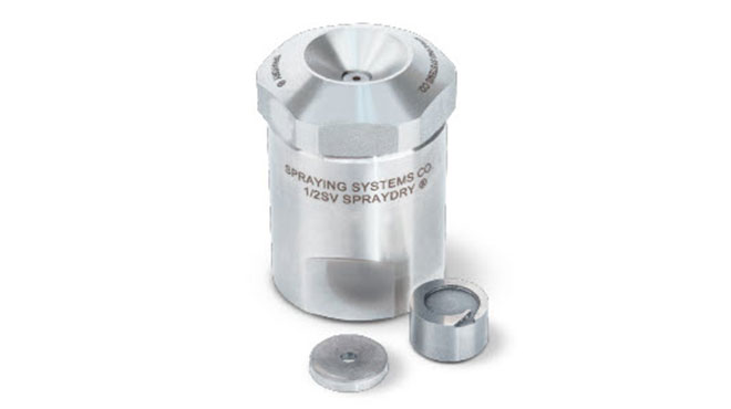
Figure 1. SV SprayDry nozzle body, with a Swirlchamber and orifice
The SB SprayDry nozzle uses a Slotted-Core insert which generates a rotating fluid by forcing the fluid through slots around the outer surface of the Slotted-Core insert, before exiting through a round orifice.
| Nozzle (abbr.) |
Part Number | Orifice Diameter mm (in.) |
Internal | P bar (psi) |
Q lpm (gph) |
| SV-6 | SVI-106YM+SVS6 | 2.70 (0.106) | Swirlchamber | 207 (3000) | 20.7 (328) |
| SV-7 | SVI-109YM+SVS7 | 2.75 (0.109) | Swirlchamber | 207 (3000) | 26.8 (424) |
| SB-40 | SIBY40+SBBY32-MFP | 2.50 (0.098) | Slotted-Core | 207 (3000) | 21.1 (334) |
| SB-42 | SIBY42+SBBY45-MFP | 2.40 (0.094) | Slotted-Core | 207 (3000) | 26.6 (421) |
| WJ-2 | AA104-1/2-AA-TCX2-8 | 4.00 (0.156) | Whirlchamber | 207 (3000) | 21.3 (338) |
| WJ-3 | AA104-1/2-AA-TCX3-7 | 3.60 (0.141) | Whirlchamber | 207 (3000) | 26.9 (426) |
| SDX3-SF | SDX III - A00703-106-SF | 2.70 (0.106) | Swirlchamber | 207 (3000) | 20.7 (328) |
| SDX3-SG | SDX III - A00703-109-SG | 2.75 (0.109) | Swirlchamber | 207 (3000) | 20.7 (328) |
| SDX5-SG | SDX V - W19581-109-SG | 2.75 (0.109) | Swirlchamber | 207 (3000) | 26.8 (424) |
Table 1. List of nozzles used for testing with abbreviated names, full part numbers, exit orifice diameters, internal geometry type, and flow rate at 3000 psi. The nozzles were selected to fall into two groups suitable for direct comparison based on flow rate at 3000 psi, noted by the non-gray/gray rows. Note, while the given abbreviations for each nozzle use a single numeral identifier, each nozzle incorporates 2 parts (the orifice and the insert), which are fully identified in the Part Number column.
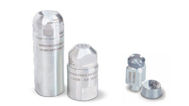
Figure 2. SB SprayDry nozzle body (left), with a Slotted-Core and orifice (right)
Figure 3. WhirlJet SprayDry nozzle body (left), with a Whirlchamber and orifice (right)
The WhirlJet SprayDry nozzle moves the liquid through one, or two, small entry ports into a tall (axially) chamber which imparts a radial flow velocity in the fluid before exiting through a round orifice. Figure 3 provides an image of the assembled WhirlJet SprayDry nozzle body as well as the Whirlchamber insert.
Each of the SprayDry nozzle types carries its own benefits and limitations. The SV SprayDry nozzle allows the lowest minimum rated flow rate (1-60 lpm at 70 bar), and allows the least change in mean drop size as the operating pressure is changed. The SB SprayDry nozzle provides the smallest mean drop size but has the smallest low-to-high rated flow rate range (3.5-35 lpm at 70 bar). The WhirlJet SprayDry nozzle provides the largest drop size at equivalent operating pressures, but has the widest rated flow rate range (3.3-85 lpm at 70 bar). The purpose of this investigation is to investigate the details of these characteristics, and to provide an explanation for these benefits given the relative similarly of each design.
Finally, while not the primary focus of this investigation, the Delavan SDXR nozzles [8] with a swirl chamber style design are also investigated.
Phase Doppler Particle Analyzer (PDPA) Setup
Spray characterization measurements were carried out with a Phase Doppler Particle Analyzer (PDPA). Manufactured by TSI Incorporated, the PDPA instrument employed fiberoptic-coupled 2D-transmitter and receiver units connected to a PDM100-2PSS and FSA3500-2P. A PowerSight solid-state laser transmitter unit provided 532 and 561 nm wavelength lasers (channels 1 & 2, respectively) with 500 mW per channel; note, measurements were only acquired using channel 1 for axial spray velocity in this investigation. The emitted laser beams were nominally 3.54 mm in diameter, although the effective diameter of the beams was significantly smaller at the measurement location due to beam focusing and the Gaussian beam effects/Probe Volume Correction (PVC) [3]. The PDPA instrument was setup using a transmitter/receiver lens combination of 500/500 mm, and the receiver located at a 40° off-axis position, which allowed for a sufficient drop size measurement range (1-375μm) and resolution. The receiver back-end focal length was 250 mm and the slit aperture was 150 μm. For the current investigations, the somewhat large slit aperture is expected to offset uniform droplet trajectory errors in probe volume area measurement [5]. The FlowSizer-64 experiment manager and hardware control software was used to control and process the results.
Figure 4. PDPA and nozzle setup with coordinate system definition
Measurements of droplet size, axial velocity, and local volume flux were acquired across the +x axis of each spray plume; the general setup of the instrument, nozzle, and coordinate system are shown in Figure 4. All PDPA measurements were acquired at 48 inches from the nozzle and ranged from the spray center (x,y)=(0,0) to the edge, at 10 mm increments; resulting in roughly 15 points per nozzle/condition. 10,000 samples were acquired at each point to provide converged statistical values (±1%). The high-power PowerSight laser provided a sufficient laser intensity to offset spray density limitations in the signal-to-noise ratio. The methods used for the PDPA measurements of droplet size and velocity were consistent with those identified in the PDPA manual [9].
Post-Processing Methods
Weighted averaging is a reasonable and robust method for combining many individual point-measurements into meaningful combined statistics; and in this case, planar-statistics. The methods used to generate weighted average values which are representative of the planar spray plume characteristics follow typical mathematical processes, and are identified in detail by Bade and Schick [4]. For the purposes of this paper, two weighting parameters are used in the post-processing of the point-wise data and each represents a relevant physical characteristics of the investigated spray plumes: i ) the discrete area that each measurement point is expected to represent, and ii ) the local volume ux at the location of each measurement. The use of the two parameters together weight the averaged results toward the spray characteristics where the majority of the sprayed volume is present. The phase Doppler method allows accurate simultaneous measurement of drop size, velocity, and volume ux [5] and therefore allows these weighting methods to be imple mented efficiently without additional measurements or assumptions. Furthermore, drop size distributions are acquired at each point using the PDPA, and these point-wise-distributions are combined using the methods outlined by Bade and Schick [4][6] to generate planar-representative drop size distributions.
In order to allow a comparison of the drop size distribution width, the Relative Span Factor (RSF) [2] is employed, where
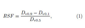
and Dv0.1, Dv0.5, and Dv0.9 represent the cumulative volume percentage drop size values [2].
1Note that there is only a single point at 3000 psi provided for the SDX3-SG nozzle, and falls just below the SV-7 result.
Results and Discussion
The results of this study are organized into subsections which highlight the effect of pressure, the effect of nozzle type, and the effect of nozzle capacity. Note, for the purposes of brevity, only select nozzles from Table 1 are presented to support the discussion in each section, which are noted in the legend of each figure.
Effect of Pressure
In this section, the effect of operating pressure is investigated for the nozzles selected based on matching flow rate at 3000 psi for the low capacity target (21 lpm). Figure 5 presents the Median Volume Diameter (MVD or Dv0.5) for the low capacity nozzles over a range of operating pressures. As expected, the average drop size decreases with increasing pressure. The SB-40 nozzle produces the smallest Dv0.5 drop size results, as well as the narrowest drop size distributions according to the RSF results shown in Figure 6. The small drop size generated by the SB-40 nozzle correlates well with the highest axial velocities, Vz, from any of the nozzle types, as shown in Figure 7. The SV-6 nozzle produces the largest average drop size at each pressure, by about 14% relative to the SB-40 nozzle, and the SDX3-SF is larger than the SB-40 by about 7%. All nozzles demonstrate an increase in axial velocity with operating pressure. The SV-6 nozzle has a lower velocity than the SDX3-SF by about 16%, and a much lower velocity than the SB-40 by about 40%. The low axial velocities may result in longer residence times in the spray drying tower, which would likely beneficial, but would need to be balanced properly with the larger average drop sizes.
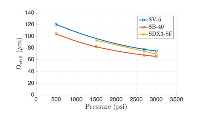
Figure 5. Pressure vs. Median Volume Diameter for the low capacity nozzles
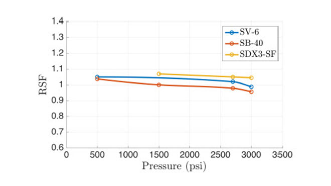
Figure 6. Pressure vs. Relative Span Factor for the low capacity nozzles
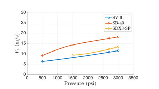
Figure 7. Pressure vs. Axial Velocity for the low capacity nozzles
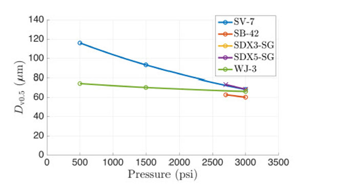
Figure 8. Pressure vs. Median Volume Diameter for the high capacity nozzles
The general trends and relative difference between each nozzle at the various pressures may be explained based on the internal geometry of each nozzle. The SB nozzle-type employs two grooved channels on the Slotted-Core insert to impart swirl in the passing liquid flow, which leads to increased fluid velocity (and likely turbulence) before exiting the nozzle body. These high velocity channels lead to additional breakup of the liquid stream into smaller droplets, resulting in reduced droplet velocities (smaller droplets lose their velocity closer to the nozzle as they carry less momentum). Alternatively, the SV nozzle has a large Swirlchamber where all incoming fluid is forced to travel concentrically around the nozzle to the exit orifice, likely resulting in a more organized rotations (and less turbulence) and a heightened velocity outside the nozzle, with slightly larger droplets. Note, these explanations are unconfirmed, as all data was collected outside the nozzles and downstream of the atomization region. In the case of the SV and SB nozzles, the RSF=1.0±5% across all pressures, and for the SDX3-SF the RSF=1.07±2% across all pressures. In the subsequent sections, the results obtained at the 3000 psi operating pressure become the focus of the analysis, as this is most representative of a typical operating pressure in most spray drying processes.
In Figure 8 the Dv0.5 results for the high capacity nozzles are provided. The results for the SV-7, SB-42, and SDX3-SG1 all demonstrate very similar trends to their respective style low flow nozzles presented in Figure 5; therefore, no further analysis is provided. The WhirlJet nozzle (WJ) provides a Dv0.5 somewhere between the SV and SB nozzles, and likely a smaller drop size than the SB nozzle at lower pressure; unfortunately data was not acquired to demonstrate this explicitly. Dv0.5 for the WhirlJet nozzle demonstrates a small decrease with an increase in pressure, which provides a uniquely weak effect of pressure on the resulting Dv0.5. Finally, the SDX5-SG nozzle demonstrates a nearly identical Dv0.5 to the SV-7 nozzle, at the high-pressures that were tested2.
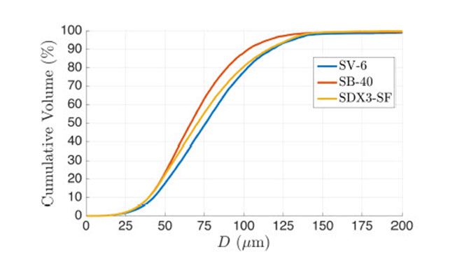
Figure 9. Cumulative volume drop size distribution for the low capacity nozzles at 3000 psi
Effect of Nozzle Type
In this section, the details of the drop size distributions for the nozzles selected for low & high flow rates at 3000 psi are presented and discussed, as well as the point-wise Dv0.5 results for the low capacity nozzles. In Figure 9, the cumulative volume percentage drop size distributions are presented for the low flow nozzles discussed in the previous section at the 3000 psi operating condition. The Dv0.5 values for each nozzle (50% point in Figure 9) are clearly visible demonstrating the `average' drop size for each nozzle. Perhaps more interestingly, the width and slope of each distribution can be seen and compared to the RSF results of Figure 6. Clearly, the SB-40 nozzle generates the narrowest and steepest drop size distribution, while the Delavan SDX3-SF has the widest.
In order to examine the details of the spray plume generated by each nozzle, Figure 10 provides the point-by-point Dv0.5 and Vz results for each of the nozzle of Figure 9. Note that it is expected that all of the investigated spray plumes will be axisymmetric, therefore, only a single line of measurement points was acquired from the nozzle centerline (x=0) to the spray edge (x>0). First, the Dv0.5 results near the nozzle centerline, for all three nozzles, are nearly identical; the differences appear as the spray edge is approached with the order of largest to smallest following that of the overall weighted Dv0.5 values of SV-6 > SDX3-SF > SB-40. Also, the spray plume width is slightly smaller for the SV nozzle. The Vz results for all three nozzles are highest at the nozzle centerline, and decrease with radial location. Interestingly, the SB nozzle exhibits a slightly lower-than-maximum velocity at the nozzle centerline and reaches its maximum axial velocity at a radial location of 20% of the plume radius.
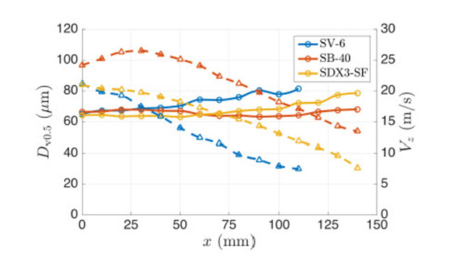
Figure 10. Point-wise Dv0.5 and Vz data for the low capacity nozzles at 3000 psi. Note that the Dv0.5 results are presented with circles+solid lines, while the Vz data are presented with triangles+dashed lines.
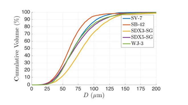
Figure 11. Cumulative volume drop size distribution for the high capacity nozzles at 3000 psi
The cumulative volume drop size distributions for the high flow rate nozzles operating at 3000 psi are presented in Figure 11. Similar to the low capacity nozzle results, the SB type nozzle (SB-42 in Fig. 11) exhibits the smallest drop size and the narrowest distribution (steepest slope). The SV-7, WhirlJet (WJ-3), and SDX5-SG nozzles all demonstrate a similar average drop size and distribution width, while the SDX3-SG nozzle generates a similar distribution width but the largest average and maximum drop sizes.
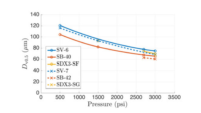
Figure 12. Cumulative volume drop size distribution for low (circle-markers and solid-lines) and high (x-markers and dashed-lines) capacity nozzles
Effect of Nozzle Capacity
In Figure 12, the effect of capacity is examined with various nozzle styles over a range of pressures. Interestingly, the Dv0.5 values are larger for the low capacity nozzles. This goes against the typical assumption that a larger nozzle capacity leads to a larger droplet spray. To be clear, the larger capacity nozzles investigated here (SV-7, SB-42, and SDX3-SG) all have a larger exit orifice diameter than their smaller counterparts (SV-6, SB-40, SDX3-SF), and thus produce a larger flow rate at a given pressure. No explanation for this trend can be proven from these results, but one theory is that the increased total flow rate of the high capacity nozzles would generate stronger air-entrainment in the spray plume. The increased entrained air flow causes the droplets to maintain a higher velocity further from the nozzles. The entrained air flow would have a greater influence on the low-momentum small droplets which would otherwise tend to decrease in velocity faster in the low capacity spray, this could cause the flux-sampling PDPA measurement to collect a higher small-to-large droplet ratio; resulting in smaller drop size statistics. This admittedly unsubstantiated explanation will be the focus of a future investigation.
Conclusions
The purpose of this study was to investigate the average drop size, average velocity, and drop size distribution width of standard spray dry nozzles used in many industrial applications. It is found that the SB SprayDry® nozzles with the Slotted-Core insert produce the smallest average drop sizes, smallest maximum drop sizes, and narrowest drop size distributions; while also generating the largest axial velocities. The SV SprayDry® nozzles with the Swirlchamber produces a somewhat larger average droplet size but also delivers the smallest axial velocities. The WhirlJet® SprayDry® nozzles create a drop size somewhere between the SB and SV nozzle types, but provides the least change in average drop size over the range of tested operating pressures. It is shown that the SDX3-SF and SDX3-SG nozzles produce an average drop size somewhere between or larger than the SB and SV type nozzles; furthermore, the drop size distribution and RSF are shown to be wider than the SB, SV, and WhirlJet SprayDry nozzles. The SDX5-SG nozzle demonstrates similar drop size characteristics to the SV-7 SprayDry nozzle.
The point-wise results provide insight as to where the drop size differences exist within the spray plumes. The different nozzle types seem to produce similar average droplet sizes at the spray centerline, but deviate to larger or smaller droplets near the spray edge.
Finally, it is found that larger capacity nozzles generate a smaller Dv0.5 drop size result than equivalent nozzle types of a smaller capacity. Even though the difference in Dv0.5 is small, this result is counterintuitive, and is as-of-yet unexplained. The direct implications of these results are limited by the fact the testing has only been conducted with water at this time, and typical processes will require much more viscous fluids to be sprayed, often with high solids content. However, these considerations do not eliminate the usefulness of these analyses, and characterizations with more viscous sprays, would be expected to simply have exaggerated differences.
Acknowledgements
The authors would like to thank Ben Bridges of Spraying Systems Co. for his extensive work on data collection and post-processing in support of this investigation, as well as Rich Kassinits of Spraying Systems Co. for his efforts in support of this work.
References
[1] Masters, K., Spray Drying Handbook, 4th Ed., George Gowdin, London, ISBN 0-7114-5805-7, 1985.
[2] Lefebvre, A. H., Atomization and Sprays, Combustion: An International Series, Hemisphere Publishing Corporation, 1989.
[3] Albrecht, H.-E., Borys, M., Damaschke, N., Tropea, C., Laser Doppler and Phase Doppler Measurement Techniques, SpringerVerlag Berlin Heidelberg, 2003.
[4] Bade, K. M., Schick, R. J., Generating Planar Statistics from Point Measurements in a Spray, Atomization and Sprays, 2016. (DOI:10.1615/AtomizSpr.2015013836)
[5] Bade, K. M., Schick, R. J., Phase Doppler Interferometry Volume Flux Sensitivity to Parametric Settings and Droplet Trajectory, Atomization and Sprays, vol. 21, issue 7, pp. 537-551, 2011.
[6] Bade, K. M., Schick, R. J., On Generating Combined Drop Size Distributions from Point Measurements in a Spray, ICLASS - 13th Triennial International Conference on Liquid Atomization and Spray Systems, Tainan, Taiwan, August 23-27, 2015.
[7] Spraying Systems Co. , SprayDry® Nozzles, Bulletin No. 695A, 2014.
[8] Delavan® Spray Technologies, SDX® Spray Dry Nozzles Product Guide, SDX® Product Brochure, Version 2.0, 2008.
[9] TSI Incorporated, Phase Doppler Particle Analyzer (PDPA)/Laser Doppler Velocimeter (LDV), Operations Manual, Rev J, 2012.
SprayDry® is a registered trademark of Spraying Systems Co.