
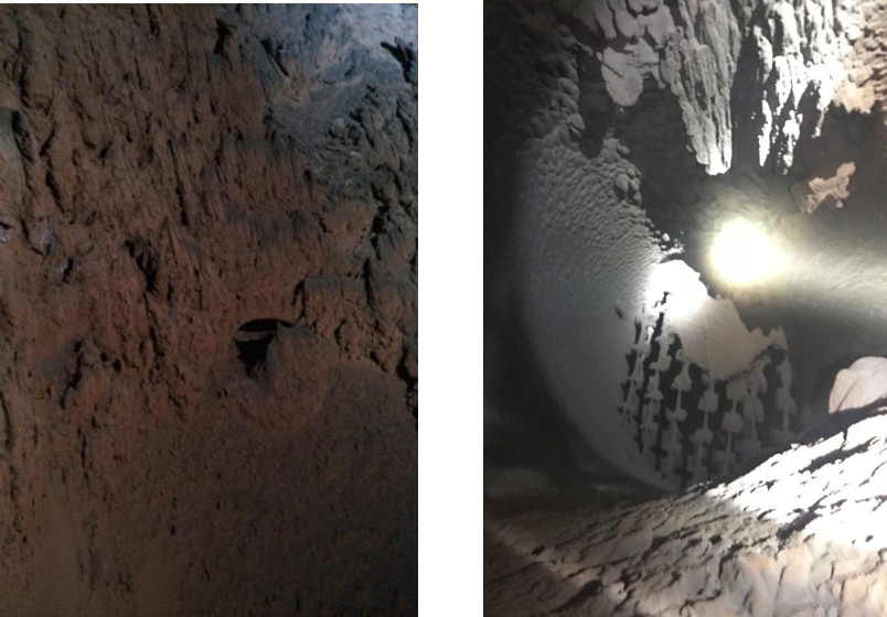
Severe dust lumping (shown here), extended maintenance downtime and profit stagnation caused one steel company to seek a better solution for their basic oxygen furnace (BOF). Due to the hazardous conditions and risk of physical testing, the company sought our CFD services to optimize the application.
Steelmaking: The Basics
In the steelmaking process, a BOF refines molten pig iron and scrap into steel. This process typically involves multiple stages but starts with scrap and molten pig iron entering a blast furnace. This process generates significant ash, soot, and other pollutants, which then enter the BOF’s evaporative cooling tower through a duct. In the evaporative cooling tower, the gas enters the tower’s apex where it is quickly and powerfully cooled by a spray.
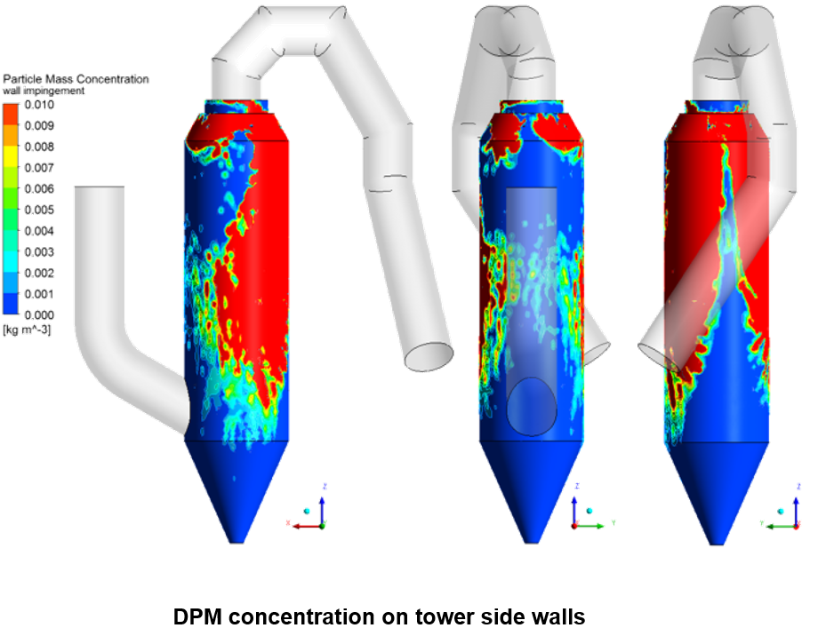
The polluted dust, entrained in the gas, then falls to the tower’s base where it’s incinerated. If the spray lance layout is flawed, however, as was the case with this customer, severe dust lumping occurs. This means the spray that collides with the incoming gas, but does not evaporate, sticks to the wall and collects dust, as shown below. The red area is water that has not evaporated and is stuck to the walls collecting dust.
If this process continues without stopping to clean the dust off the tower walls, spray continues to collect on the sticky dust and collects more and more dust. Eventually, the company is forced to halt the process for maintenance. This downtime results in worker health issues, lost profits, and unsustainable business practices.
Optimizing the Process Using CFD
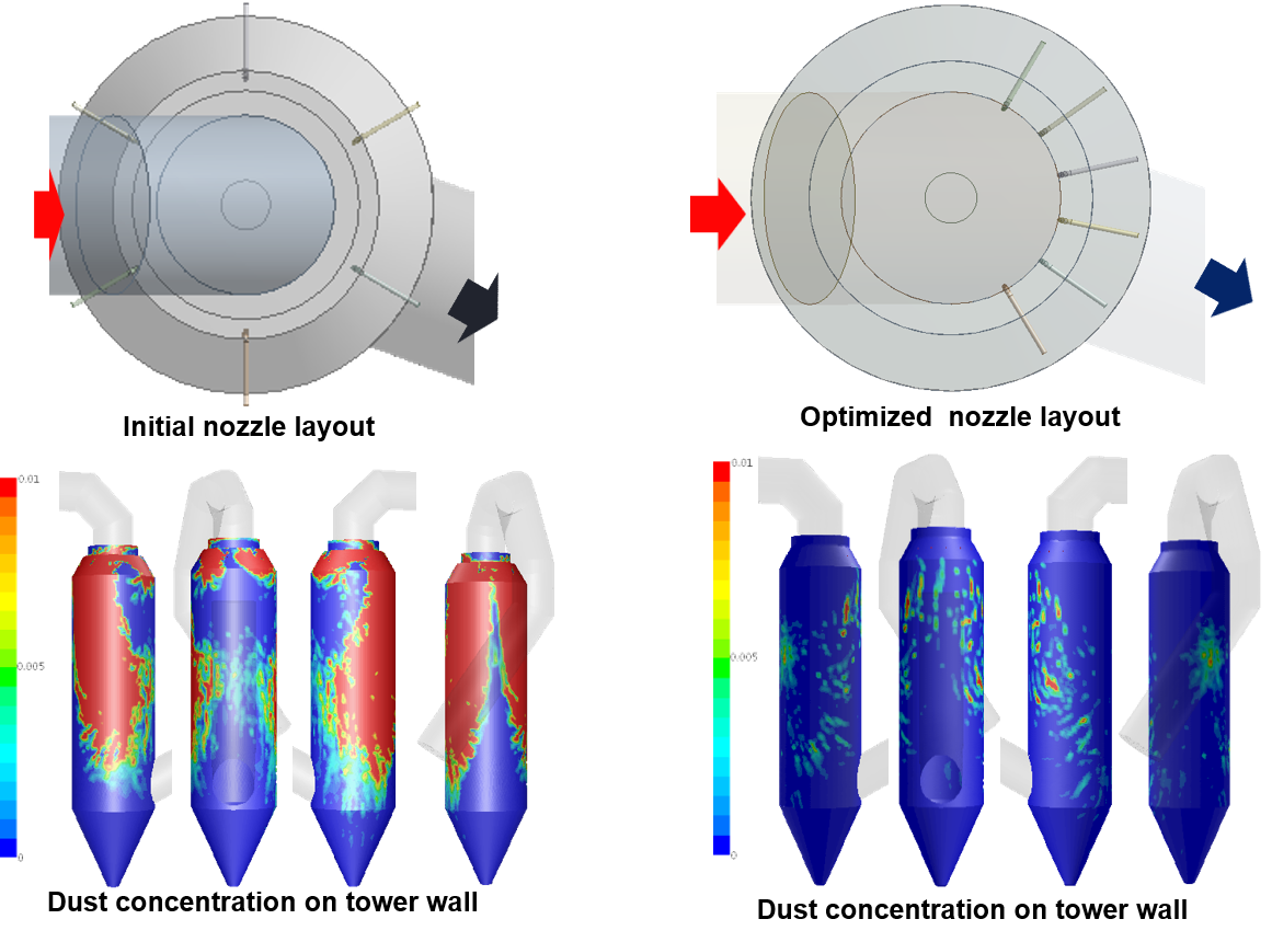
Our task was to design an optimal nozzle layout, so the spray would meet the gas at the tower’s entrance and evaporate completely, so dust would fall to the tower bottom where it would be appropriately incinerated. We had to do this with minimizing wall wetting and short time and space domains in mind.
In this process, conventional nozzle layout designs place six injectors at evenly spaced increments along the circular cooling tower wall just as the gas enters the tower. Rather than follow conventional thinking, as this was clearly causing our customer severe problems, we wanted answers to questions such as: How should we lay out the nozzles? At what depth should they be inserted for this particular tower? Is there an optimal injection and spray angle?
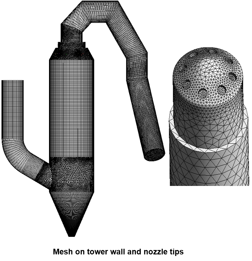
To answer these, we first meshed the entire tower, the inlet and exit ducts, and the nozzle lances. This allowed our CFD software to perform advanced flow mechanics calculations at small, finite points throughout the entire application. We could then assess both what was happening during the current process, as well as, the nozzle layout design that would optimize the evaporative cooling tower process.
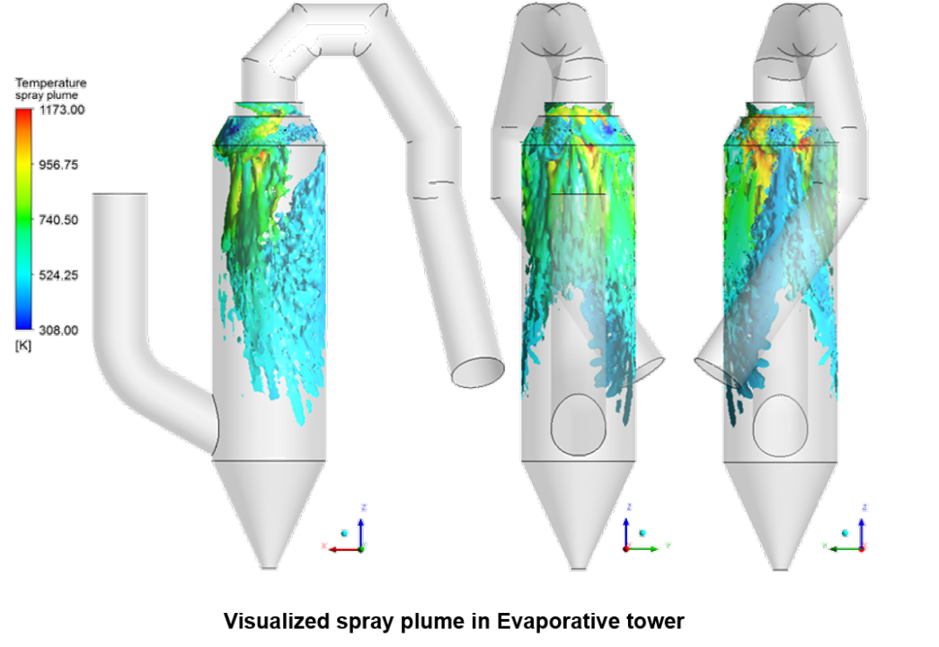
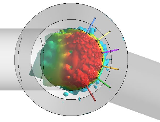
When we visualized the spray plume colored by temperature gradients, shown below, we found that six nozzle lances situated at close intervals directly opposite the gas inlet effectively evaporated the spray and prevented wall wetting. Furthermore, this nozzle layout significantly reduced dust lumping throughout the tower.
ROI and Continuous Improvement
Using the results, this company benefited from decreased maintenance downtime, higher yield, and greater employee safety. In environments like this, where physical testing is impossible, our CFD services offer a solution unmatched by other modeling software.
The basic oxygen furnace is just a single location where CFD proved helpful for this customer. Considering the hazardous environments of most steel plants, we implement testing and CFD solutions for customers in a wide range of steel applications and throughout the steelmaking process.
If you’d like to discuss the topic more in depth please contact us or connect with me directly via LinkedIn.
For more CFD simulations please visit our YouTube page!